Quantization in PCM with example
QUANTIZATION
The PCM signal is generated by carrying out following basic operations:
- Band limiting (using LPF)
- Sampling
- Quantizing
- Encoding
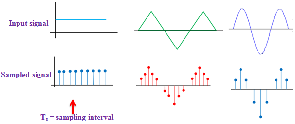
Two fundamental processes are involved in the generation of a PCM signal: sampling and quantization. Sampling is time discretization and quantization is amplitude discretization.
In PCM, conversion of analog signal to digital signal is done in two steps
- Sampling
- Quantization
Below figure shows sampling step:

Quantization is the process of rounding of the sample value to the nearest quantization level. Remember that number of quantization levels is predefined.
If n = number of bits used to represent the sample
Then, q = number of quantization levels
= 2n


Quantizing 0.4 V sample value: See that level 2 is near to 0.4 V. So, for sample voltage 0.4 V, 01 code is transmitted.
Quantization error e = 0.4 – 0.375 = 0.025 V
Quantizing 0.78 V sample: Level 4 is nearest to 0.78 V. So, digital code 11 is transmitted.
Quantization error e = 0.875 -0.78 = 0.095 V
NOTE:
Quantization process introduces a certain amount of error or distortion. This error known as quantization noise and is minimised by increasing the number of quantization levels. But increasing number of quantization levels increases number of bits to represents each sample and hence increases bit rate and cost of transmission.