(2,1,1) convolutional code |solved problem |state diagram
Q. Below figure depicts a rate ½, constraint length L = 1, convolutional encoder. Sketch the State diagram. Also find encoder output for input data: 11101
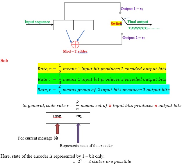
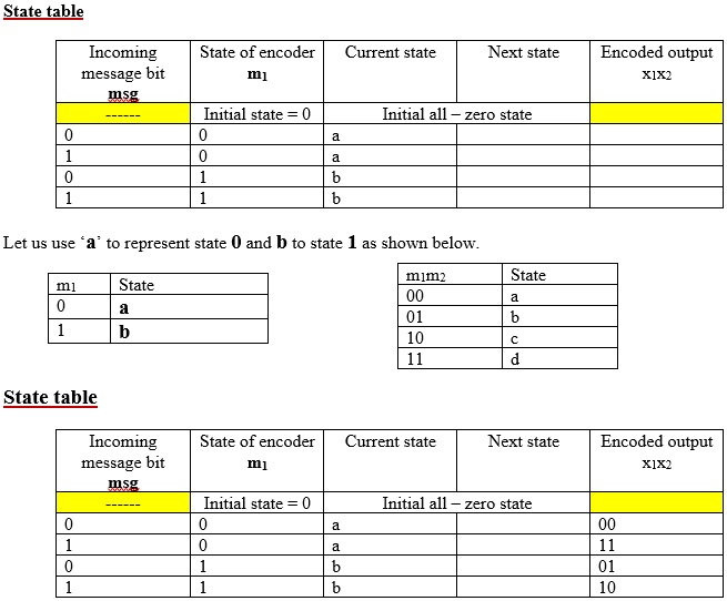
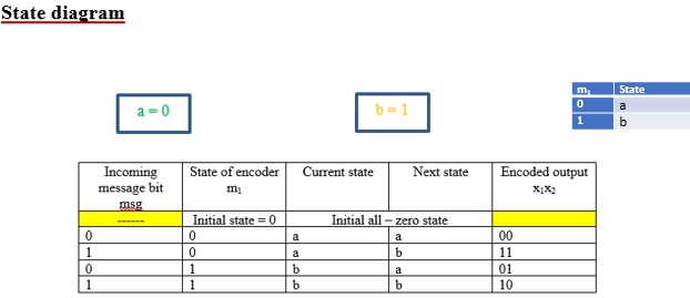
If 2 bits are used for state, the 22 = 4 states are possible
If 3 bits are used for state, the 23 = 8 states are possible
If 4 bits are used for state, the 24 = 16 states are possible

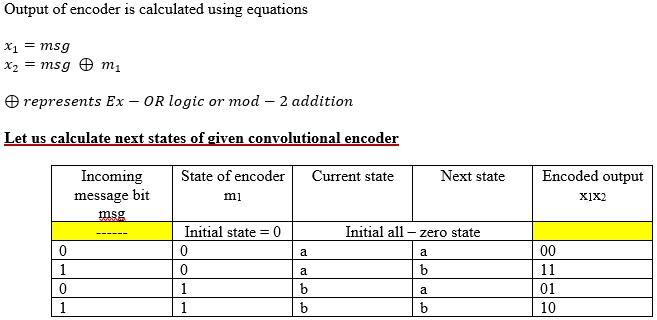
Finding encoded output from STATE diagram
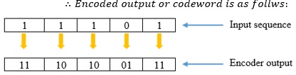
Let’s us assume input sequence m = 11101
Initially start from all-zero state i.e., a = 0
Step 1: Initially, we are at state a. Check that 1st message bit = 1. See from node a. For bit 1 state changes from node a to b (Red line) and output = 11.
Step 2: Now we are at node b. Check that 2nd message bit = 1. See from node b. For bit 1 state changes from b to b (Red line) and output = 10.
Step 3: Now we are at node b. Check that 3rd message bit = 1. See from node b. For bit 1 state changes from b to b (Red line) and output = 10.
Step 4: Now we are at node b. Check that 4th message bit = 0. See from node b. For bit 0 state changes from b to a (Black line) and output = 01.
Step 5: Now we are at node a. Check that 5th message bit = 1. See from node a. For bit 1 state changes from a to b (Red line) and output = 11.
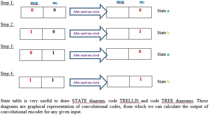
Graphical representation of Convolutional codes
3 different but related graphical representations can be used to study of convolutional encoding.
- Code tree = Tree diagram
- Code trellis = Trellis diagram
- State diagram
Note that we can easily find output of the encoder from any of the above diagrams.
Given a sequence of message bits and the initial state, you can use any of following 3 diagrams to find the resulting output bits.
State diagram
For convolutional encoders, it is sometimes useful to draw the state transition diagram. The nodes of the figure represent the 4 possible states of the encoder, with each node having 2 incoming branches and 2 outgoing branches.
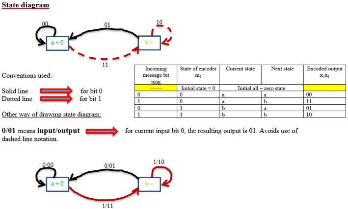
- A transition from one state to another in response to input 0 is represented by a solid branch.
- A transition in response to 1 is represented by a dashed line.
- The binary label on each branch represents the encoder’s output as it moves from one state to other.
With the help of state diagram, we can determine the output of the encoder for any incoming message sequence. We simply start at state ‘a’, the all zero initial state and walk through the state diagram in accordance with the message sequence. We follow a solid branch if the input is a zero and the dashed branch if it is a 1.
Because a convolutional encoder has finite memory, it can easily be represented by a state transition diagram. In this diagram, each state of the convolutional encoder is represented by a box and transitions between states are denoted by lines connecting these boxes. On each line both the input causing that transition and the corresponding output are specified.
The number of lines emerging from each state is equal to the number of possible inputs to the encoder at that state, which is equal to 2k.
The number of lines merging at each state is equal to the number of states from which a transition is possible to this state. This again equal to 2k.